Willem Toet explains…..Air ducts
I’d like this to be a simple guide to improving some parts of your race car wherever you need to provide passively induced “forced” airflow. Aerodynamicists learn all about the theory and that’s useful for sure and important when pushing the boundaries of the possible, but not vital if you have a slightly less advanced airflow related job to do. I hope that this can give you a head start without needing years of study. It isn’t always super easy and I can’t cover everything here, but here are some practical tips.
Ducts are there to capture air from, ideally, a clean, high energy source and conduct it to the place it needs to be used (usually for cooling of some sort, or for “feeding” an engine).

This Mini picked up air for the engine from the engine bay. The carburettor entries are behind the engine and above the exhaust so clearly not an ideal location if the weather is already warm. As the car was used for hillclimbing (by good friend Richard Marshall) and didn’t need headlights, Richard (with some guidance from someone who knows a bit about aerodynamics) made an entry and an expander to supply the engine with cool, high pressure air. The entry was sized to ensure that the engine was not “choked” except at much lower than wheelspin limiting vehicle speed, and a nice long gentle expander was installed which fed a new purpose made “airbox”. The white material surrounding the duct is an insulator. It is rare though to have enough space to do this. To be honest I think this is actually a lovely example. Nice radius on the leading edge to ensure there is nothing to trip up the air and the expander is a low angle. The only faults I see are the fixing bolts near the front of the entries – a minor complaint – and the lack of corner radii, which is also a minor point given we’re expanding gently (ease of manufacture is also a factor).

Richard Marshall commented: “If I remember correctly we did some pressure logging on the installation and it generated positive pressure at exactly the design vehicle/engine speed.”
The duct was added in about 1990. Richard was already designing his own data logging systems back then so it was natural that he’d want to measure the impact the duct had.
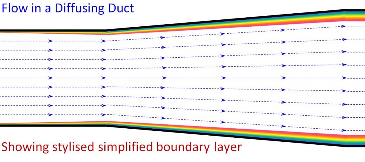
There are plenty of scientific articles out there that will explain that you need no more than 7 degrees for an expanding duct like this. Why expand? Basically because you can use the speed of the vehicle to convert that speed energy (we call it total pressure) in to static pressure (think of it as pressure that pushes on surfaces if any are there) and into air density. More density means more air (oxygen molecules in this case is the important bit) gets into the engine (and in this case it is also cooler = even more density).
Two early diffusing ducts have stuck in my mind because of their surprising (at the time) impact on performance. One was for the brakes and driver cooling of the Lord Downe owned Aston Martin Nimrod (1983). In order to pay some respect to the styling of the traditional Aston grille, we put two oval entries for cooling low down beside the main radiator entry at the front of the car. This was the perfect size (not luck) for two 50 mm (I think) diameter ducts (on each side). We simply connected wire reinforced flexible ducting (known colloquially as donkey dick): one to cool the brakes and one to blow air into the cockpit for the driver.

Unfortunately, the brakes overheated and the driver was feeling pretty cooked as well. Something had to be done, and quickly. With some experienced advice we put an expander (a diffuser) behind the entry. As with all retrofitted parts, space was at a premium. To make the area large enough to go out to three ducts of the same size as the original two, we just didn’t have the length (clearance to existing mechanical components) to achieve the area we wanted. We had no choice but to expand faster than the recommended max of 7 degrees.
We went to a pretty aggressive angle, of something like 15 degrees, in one plane only which was never going to stay attached, but we added two splitters to control the expansion in each part of the duct to about 5 degrees. We didn’t have the tools, or the time, to experiment. When tested this felt like a miracle. The driver commented that he felt like he was being blown out of the cockpit and the brakes ran well within the limits of the temperature paint we put onto the rim of the disks (unlike before). It seemed a miracle from the driver’s perspective because we were picking the air up from the same place, giving him a third of the air rather than a half, but more came through. However, we’d increased the pressure in the duct to above the level of the cockpit, and that made all the difference. In fact, at Le Mans we lost a door on the main straight at top speed (literally blew off due to the pressure difference inside to outside) and had to reinforce the attachments! Perhaps that’s one reason I remember the expanders!
A word of caution about splitters! Splitters in a duct are usually simple fabricated flat sheets of material (we used aluminium). A sharp leading edge can lead to separation right there at the leading edge if the airflow is not aligned. I suggest that a splitter should start where you have high confidence of the flow angularity to minimise the risk of that. In addition, there is a certain amount of skin friction on both sides of any sheet, so that too has to be taken into account if you put splitters into a duct. A longer duct of low expansion angle is slightly better than a shorter duct of double the angle with a splitter, because the skin friction causes the growth of a “boundary layer” which grows at a non linear rate (fast growth at first). Hence, if you are designing a duct from scratch, play with the length and expansion rate to try to minimise the number of splitters so you get each branch of a duct down to about 7 degrees. Note that radiator ducts are different because of the blockage caused by the core of the radiator.
It isn’t worth concerning yourselves too much about boundary layers but they are important. Air flowing near a surface is slowed – you can think of it as feeling friction. Surface finishes can change the way boundary layers form and behave, but the effect is usually minor compared to the shapes involved and possibly the subject of some future posts – and now we’re starting to get a bit scientific…..
Another duct expander/diffuser I remember well (because it was free performance, but also because it made the team manager sick [he looked a pale shade of green to me after testing]), was fitted to the Nimrod airbox entries – I will explain.
We had a small airbox on the Nimrods which were fed air by genuine NACA design ducts. I say genuine because most NACA style ducts you see on race cars are nothing of the sort. This statement particularly applies to those you can buy on line for motorsport applications. A NACA duct works well with sharp side edges to allow a side vortex to form – rarely seen in lower levels of motorsport. In fact, you can gain cooling performance at the cost of drag by adding a trip to the side edges. How the duct is closed is also an important (often ignored) design feature. Once the duct is closed, an expander is needed to convert dynamic pressure (speed/energy) into static (think of it as surface) pressure. That is also what is missing from commercially available ducts. The Nimrod had some carefully sculpted NACA ducts in the chassis /cockpit roof to feed the engine airbox. It was quite a struggle to fit them in with the roll cage, but it fitted where it touched let’s say. However, the chassis finished just rearward of the closing of the ducts. For this reason the initial car had the airbox fed by these shortened expanders/diffusers with the engine cover finishing the seal of the open topped airbox.
Some of us were pushing to fit simple fabricated diffusers onto the back of the NACA ducts in a way that would be compatible with the removal of the engine cover and give the ducts a better chance of feeding the engine with high pressure air. Sceptics in the team were not convinced that it would make any difference at all. So on a publicity day when it was possible for people to have “taxi” rides it was decided that Richard Williams (our team manager) would sit in the car for a back-to-back run to assess the performance of our extended diffusers. The method chosen was to have a long, clear, flexible plastic tube going from the cockpit into the engine airbox.
Inside the cockpit Richard would hold the long section of tubing into a U shape. The lower half of the U was filled with water (before we attached one end to the airbox). If the airbox had high pressure it would start to push the water away from the engine (into the cockpit). If it had suction it would suck the water towards the engine. The reference pressure would be whatever the cockpit pressure would be.
Not terribly scientific but worth a shot for a back-to-back test as we didn’t have any data logging as such back then. Richard had his thumb at the ready to seal the open end. Ray (Mallock) would do a lap with the non extended arrangement with Richard trying to see if there was any significant displacement of the water on the straights. We agreed a standard limiting rpm in top gear on the straights so we had a consistent reading and Ray has always been good at details such as that. We would then fit the diffusing extenders and the test would be repeated.
There was relatively little water displacement without the extenders and to be honest I don’t remember in which direction the water moved for that baseline test. Richard was feeling sick (wanting to throw up) from being thrown around in the race car while trying desperately to concentrate on water levels in clear plastic tubes. I’m not even sure if we had a real seat on the passenger side so he was having to hold on to the roll bars at the same time – quite a challenge!
With the expander fitted, a second run was done and the difference was significant and clear. Richard nearly had a small shower as the water was being pushed away from the engine into the cockpit. That was the end of the discussion regarding diffusing extenders – they were a standard fitment from that point on.

The expanders (but not the NACA ducts, unfortunately) are visible at the top of the picture ahead of the airbox. Image thanks to AMR1.uk and “Vantage Summer 2014”.
Some other comments about ducting air!
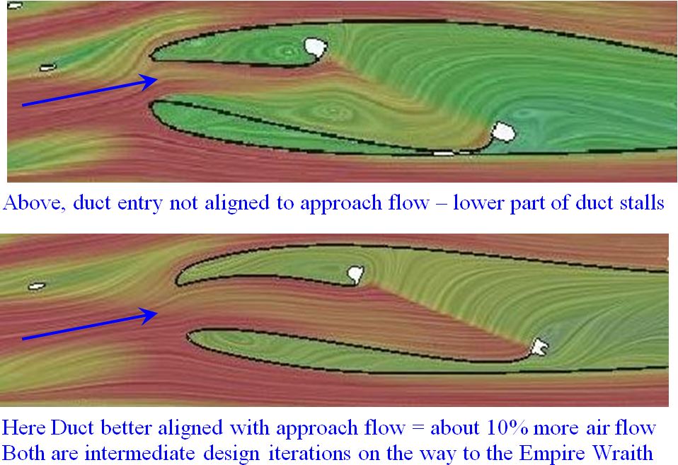
The entry is a very important thing and sizing the entry is part of it. Don’t be tempted to go for a monster entry to try to “ram” air into something – it isn’t the way to go. Air is not going to speed up to faster than the car if there is blockage in the duct further down the line, as there always is with brake ducts or radiator ducts. It is quite likely that air will flow in fast where the approach air is high speed (energy) or high static pressure to start with, and will slow down or may even (in some cases) go backwards if there are parts of a duct entry that are being “fed” by low pressure and/or low energy air. The trick is to pick the air up in a place where there is plenty of energy and pressure and then to expand it out gently and duct it to exactly where it is needed.
Be careful with the orientation of duct entries too. The entry should be aligned with the flow or you may trip the air at the entry. Where flow alignment changes during vehicle use (front wing angle changes, pitch change etc) use a bit of a radius at the leading edge to allow for changes of alignment.

Radiator cooling entries
With a fixed point of blockage (such as a radiator) you can increase the rate of expansion beyond the normal 7 degree limit as you approach the core (aerodynamic blockage) itself. It is a trick many aero people use in all sorts of applications. So use increasing expansion as you get close to the core of the radiator. It is a good strategy to do that in any case if you can. A radiator entry should be at least 20% of the area of the core for most motorsport applications. Of course this is influenced by the speed of the vehicle, the radiator area, heat rejection and so on, but that’s a good starting point. If you go significantly bigger you typically pay the price of some drag.
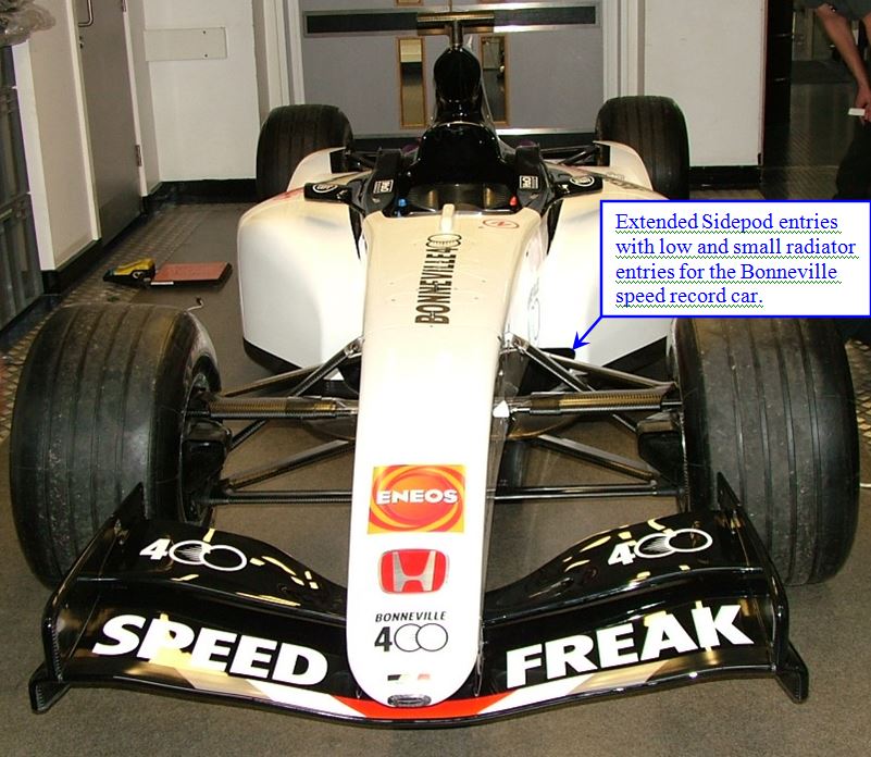
An extreme example was the BAR Honda Bonneville F1 car. I reduced the entry areas as part of the drag reduction package and just about everybody other than me was convinced it was going to overheat and would never be able to run with such a small entry. It wasn’t a problem because almost all of its running was at high speed and the heat rejection is the same as when pulling a much higher drag vehicle (so going slower but outputting the same amount of heat energy). In any case, we needed the drag reduction that the revised bodywork gave us. We needed the extra length to be able to expand the air back to the area of the radiators.

Allow at least a quarter of the radiator area for your exit(s). That’s a sensible starting point especially if you don’t have access to good CFD or wind tunnel testing resources. An exit duct adds weight and very few exist in F1. Many that I’ve tested were worse than allowing the air to find its way around the packaged essentials under the car’s bodywork – and average airspeed is very low. Hence, unless you have the tools to assess the performance of an exit duct, don’t have one – and put any exit where it will do the least damage (or the most good J). For the Empire Wraith, I tested every exit position physically possible (including a number of ducts) – out the back and out the side are the best places for that car.
In most club level motorsport people building their own cars don’t duct the air all the way to the cores of the radiators and some don’t even seal the gaps around the radiator. If you have a car like this and it has cooling problems then first seal the radiator to the bodywork so virtually all the air has to pass through the core. If that doesn’t give you enough cooling then look at ducting the air using a gently increasing expander / diffuser.
Airbox entries for motorsport
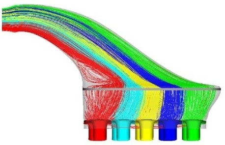
You can calculate the average air speed at the airbox entry that the engine will swallow at full throttle. For a turbo engine, multiply by the boost pressure. See my post “Control over Power”. So if you have a race car hopefully it has enough power to spin the wheels up to a certain speed. Below that speed you don’t need pressure in the airbox. A bigger entry will tend (all other things being equal) to have more drag. If you have the length of duct to be able to size your entries to a speed and still have attached flow then you’re in a good positon. Be careful with airboxes in particular – you cannot expand the air at a high rate and change its flow direction at the same time. For this and other reasons, airboxes also have increasing rates of expansion.
Think about the external shape of your ducts too as this influences the aerodynamics of the car. Think about what will happen on an airbox, in particular if the throttles are closed. In the corners you spend some time off throttle so the air must be able to find a way around the entries and still provide clean air to the rear wing. With these entries I suggest a small radius for the air entering and a lager ellipse on the exposed external shape.


