Willem Toet explains….motorsport diffusers
Willem Toet, former Head of Aerodynamics at Ferrari F1, explains the fundamental principles behind motorsport diffusers.
“Motorsport diffusers do not work in the same way as a wing in free stream, nor like a diffuser in a closed duct. Flow almost “HAS” to be 3-dimensional for them to work as we motorsport engineers make them work. Combining the diffuser and the floor ahead of it gives the most efficient aerodynamic device on most racing cars – so they’re worth understanding. To explain, I need to step back a bit to something simpler. Don’t worry, it’s not all science – it is the concepts I wish to explain. This is, though, a reasonably technical post.

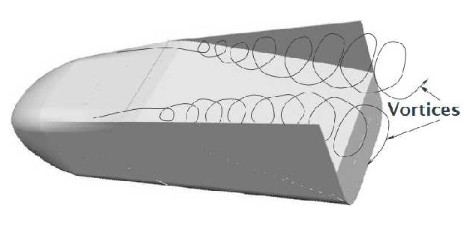
The diagram above shows the design of a bluff body with a hand sketch of the vortices that roll up along the lower edges (next to the ground).
A number of universities have conducted fundamental research, which reveals some of the secrets. I have been a visiting professor at Southampton University for many years so I will use public domain publications from their work to illustrate my explanation. Specifically I’d like to thank Professor Xin Zhang for his contribution to these studies, but many PhD students were also involved and I played my part too. There are some stages to this but, if you’re working in aerodynamics on race cars, or you really want to understand so that you can design your own diffusers, it should be worth reading on.
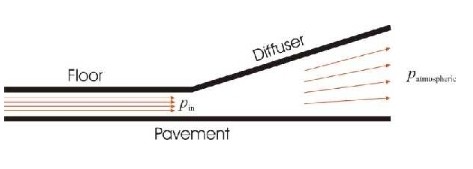
This, let’s say 2-dimensional, representation of a race car diffuser just doesn’t do it for me. There is a lot of truth in it, don’t get me wrong, but it does not explain a lot that’s important to understand.
Now this diagram does correctly predict that there is low pressure under the floor (using the Bernoulli principle). The hint also with this diagram is that the atmospheric pressure at the trailing edge influences or even dictates the pressure under the floor and there is some truth in that too. What is not clear from the plot above is the presence of, or reason for, the creation of vortices in race car diffusers.
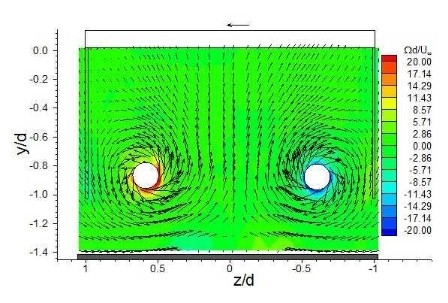
This diagram shows in plane flow movement behind the diffuser (measured using Laser Doppler Anemometry). This shows the concept of the vortex dominated flow pattern.
Basics
Diffusion in ducts is used in many industries including industrial ventilation and there are basic rules of thumb for what can be done in such a conventional, ducted diffuser. One such rule is that you cannot expand at an included angle of more than about 7 degrees.
It is possible to have high rates of expansion in ducted diffusers without stalling the flow in special circumstances, such as when there is high blockage at the end of the diffuser. This is a very special case though and normally lower angles than 7.5 degrees are needed in rectangular ducts.
Motorsport underfloor diffusers though can be made to work very well indeed with angles exceeding 20 degrees. Hence there must be something different going on.
How did, what we call, diffusers in motorsport come about?
Ground effect car underbodies were developed using end plates and mechanical means to try to bridge the gap between the underbody and the ground. In some ways the aim was to create easy to understand two-dimensional flow fields, and effectively to seal the suction inside – ie prevent ambient air from leaking in. Often this was done with a sliding skirt: a mechanism that dropped wear-resistant “rubbing strips” mounted on panels down to the ground. If these panels ever got stuck, the car was quite likely to have an accident as the downforce loss would then be substantial.
In much of the motorsport world these sort of underbodies were limited, first by imposing a ground clearance and then by imposing flat surfaces – and ground bridging devices are, largely speaking, banned. The obvious thing to try then was to start to expand the air as suddenly as is effective at the very first point along the car allowed by the regulations. That’s why lots of race teams started to work on diffusers. In my case, I realised that higher angles, than the rules of thumb would suggest, worked under the car – before I understood why – and hence the investment into university research from the teams I worked with.
Many of the concepts discussed here for flat-bottomed cars with a trailing edge diffuser also apply to shaped underbodies. So, even if you are learning about aerodynamics to work on that sort of vehicle, there are conceptual similarities.
Race car diffusers absolutely need significant airflow to work, and work best with fences which create vortices. There are other ways of generating force without much flow but these will have to wait as they aren’t as effective. Fences are set to the same height as the flat floor ahead of the diffuser so that we follow (most) motorsport regulations. Diffusers are ride height sensitive over part of the ride height range with peak performance being at a relatively low ride height. Move lower and a dramatic loss of performance and aerodynamic instability results. A high angle diffuser will have peak (downforce generating) performance at higher ride heights while a lower angle diffuser will perform best at lower ride heights. For any given set of engineering and atmospheric conditions there will be a range of diffuser angles which all achieve virtually identical peak performance (each at a different height) – as far as downforce is concerned. Peak performance is also “speed” (Reynolds number) sensitive, just in case you were beginning to think it was all a piece of cake.
How it works
By starting with a simple bluff body with a diffuser we take away some of the important but distracting interactions such as wings and wheels. This helps us to understand the fundamentals but be aware that everything is interactive and the presence of wings and wheels does change details of how these devices function.
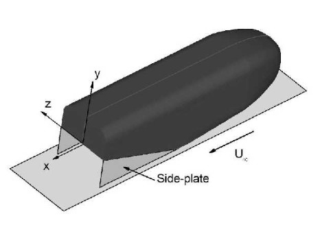
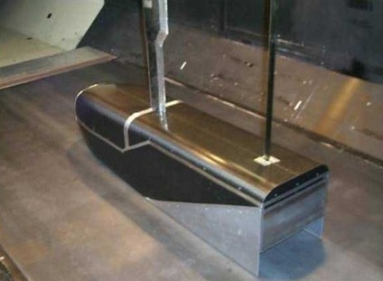
Bluff body with diffuser in the wind tunnel – note that the diffuser (angle) and fences are interchangeable. The one fitted in the picture is a low angle diffuser.
Without side plates or fences the diffuser works but with less maximum force. It is, however, interesting to see at what ride heights the diffuser without fences peaks…. A normal diffuser with fences gets most of its downforce from air passing under the choke point at the trailing edge of the flat floor = leading edge of the diffuser. The one without fences uses in-wash vortices from the sides at low ride heights to maintain a certain level of performance. Note also that this bluff body diffuser is not very wide which does have an influence on what works at what ride height.
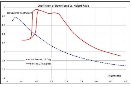
Downforce with and without outboard fences – I will explain the double curve below. In F1 there has been a trend towards ever higher rear ride heights. This may explain a small part of that although it is not the main reason.
So what are the flow mechanisms at play?
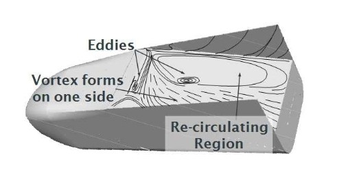
When the diffuser is reasonably far from the ground a vortex rolls up on either side of the floor. This means that additional (reasonably high energy) air is pulled in from the outside of the bluff body. There is an area of negative pressure created at near the start of the diffuser which starts the process of air rushing in, “attracted” to the low pressure region from directly beside the lower part of the body.
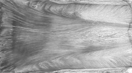
It is clear from the flow visualisation (created with a liquid painted onto the body) that the flow attached to the diffuser underside surface is not simple. I’ve had many a race mechanic try to tell me the flow is not good already when it looks like this! Plenty more criticise the design when the flow gets close to its optimum state! Downforce continues to increase as the ride height is lowered during this phase.
As the ride height is lowered further, a separation bubble forms but downforce continues to increase. Of course, the flow is not in a totally rock steady state – things are moving around a bit but still relatively stable. The width of the diffuser or part diffuser (with fences) is likely to be significant here.

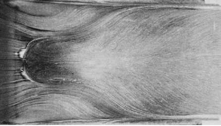
Flow is still pretty much symmetrical (although far from fully steady) for our bluff body case.
Downforce reaches its peak with flow like this. If you see such flow on your race car, you’ve done a good job – although there are further ways to optimise. Note that flow visualisation on a race car is likely to include air movements from various speeds and usually vehicle attitudes.
Then at a certain point, as the body is lowered further, one of the two vortices bursts and a sudden reduction in downforce is the result. Which one bursts first is almost random but will depend on tiny differences (eg of dynamic roll).
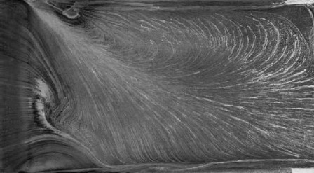
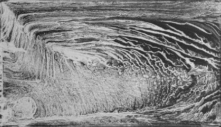
This change of flow state is significant and results in aerodynamic “hysteresis”. The two vortices hang on fairly well on the way down but, once burst, you have to come back up to a higher ride height than the burst ride to get the flow back into a nearly “symmetrical” state. The fact that burst and re-creation happen at different heights is what we call the hysteresis. This is why the plot of downforce showed two lines – they are for lowering and for raising the diffuser. Clearly drivers will hate the feel of the car if you allow it to get to these areas of performance change.
Continuing to reduce ride height further leads to reducing energy and attachment of the flow and ultimately to complete separation over the entire width of the inlet of the diffuser.
Now the next interesting detail…..
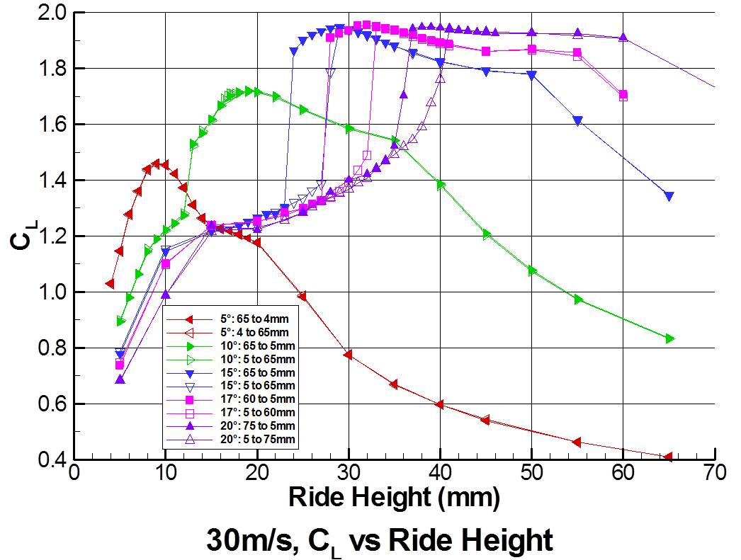
Here you can see that low angle diffusers don’t reach the same level of performance as those with higher angles (within the range tested). Once a critical level is reached the higher angle diffusers achieve the same downforce (at different heights). You can’t extend this to silly angles – we have tried! What’s interesting is that the highest angle tested has the largest ride height range at max performance. Those at slightly lower expansion angles fall away more as ride height is increased from the peak (remember 1% is a lot).
Now why might that be? Now I’m not going to give away everything I know, but one mechanism is this. If a body (or a large part of one) has substantial ground clearance then the chances are that there is air below that body which is relatively undisturbed. If true, then the higher the body, the more air is sitting there not being “used”. Conventional flow expansion in two dimensions is not going to take advantage of that energy (not “all” of it anyway).
I often talk about how much energy remains in the air. Now the truth is that the car is moving and the air is (relatively) still so what I’m really talking about is relative energy given the velocity of the car. It’s just easier to think of the air moving for an old man who’s done years of work in a wind tunnel!
The vortices rolling up under the diffuser take high energy air from the outside of the body and introduce it into the diffuser but, perhaps more importantly, they also take high energy air from below the level of the body and mix it into the body of airflow that is expanding under the diffuser.
That’s one mechanism that allows diffusers to remain attached even at high angles of attack.In Formula 1 diffusers are expanded both in side view and in plan view. This is in part because the height limit imposed by regulation is well below the aerodynamic optimum. There is still a positive impact on pressures and hence forces on the flat part of the floor. The trend towards running ever higher rear ride heights in Formula 1 will be in part because the entire floor can become a diffuser, in part because the teams have learned how to use vorticity to take advantage of all that air that otherwise passes under the car almost “unused”.
If your diffuser or floor is wide, then there may be energy in the air inboard of the outer vortices, which is not used.
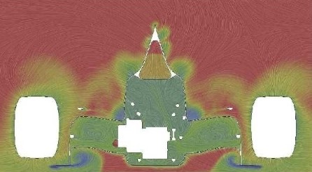
Even though this is not a conventional diffuser, you can see the vortices on the outboard parts of the floor section. The colours represent total pressure (energy) and the lines (line integrated convolution for the CFD techies) show airflow directions in the plane of the shot which is a cross section of the car near rear axle centreline. There is a lot of high energy air here not being “worked” yet and in a way the height won’t allow a single vortex to engage all of that air – a vortex has to be relatively circular in cross section.
Another little appreciated detail about motorsport diffuser performance is changing performance with speed. I won’t cover that here in detail but in the context of conventional motorsport full scale cars the impact of changing Reynolds number is relatively small. Not zero but secondary. Forces increase with speed times speed and ride height has a bigger impact than changing airflow states caused by different Reynolds numbers.
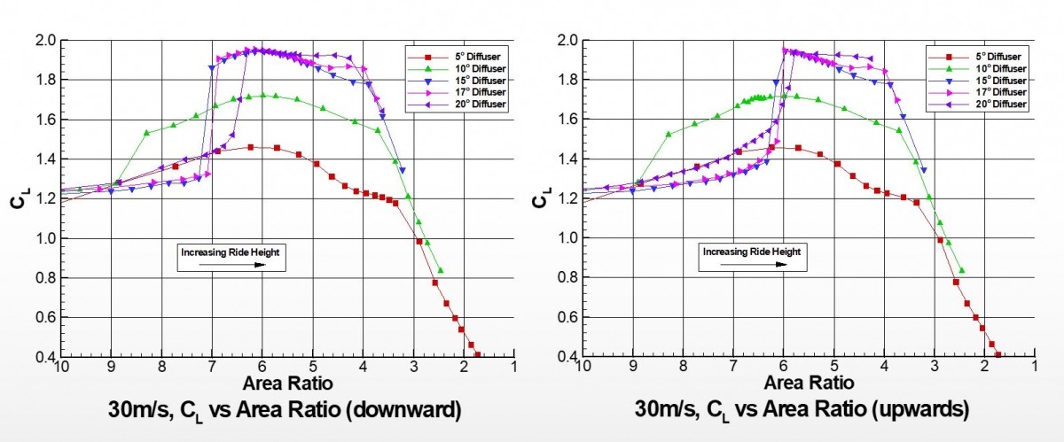
Area ratio (how much you expand the air under your diffuser) is, however, an important parameter. From the studies done at Southampton University it was found that an area ratio below 6 was relatively safe. I recommend that you don’t go above 5 unless you have F1 quality research tools and a team working aero R&D. To calculate the area ratio, calculate the area from the “choke point” of the entry to the diffuser (using the ground as the lower barrier) and the area at the trailing edge of the diffuser (again using the ground as the barrier). The ratio of those areas should not exceed 5.
F1 diffusers achieve high ratios thanks to putting the entire floor of the car at an angle…..Hence, despite centre of gravity disadvantages, one of the main reasons F1 cars have high rake. The rules don’t allow high expansion due to a limit rear of diffuser height (relative to the floor) imposed by the rules. So they just angle the floor. This same flat floor slope also lowers the front wing, which is held artificially high by the rules and that’s the other main reason for high rake in F1. Remember that F1 teams have the tools to take this basic understanding of diffuser behaviour to a higher level than I’ve explained here.
Now to make the floor/diffuser to the next stage of performance you use other aerodynamic tricks such as surrounding the floor with suction. Depending on the formula in which you race this could be by putting a wing above and slightly behind the diffuser (not legal in F1) or it could be just surrounding the it with deflectors and winglets as is the present practice in F1.
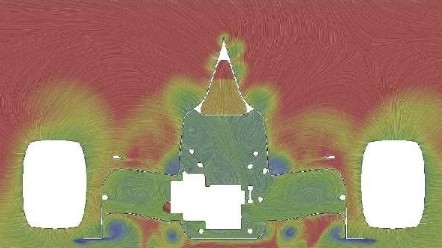
Now to make the floor/diffuser to the next stage of performance you use other aerodynamic tricks such as surrounding the floor with suction. Depending on the formula in which you race this could be by putting a wing above and slightly behind the diffuser (not legal in F1) or it could be just surrounding the it with deflectors and winglets as is the present practice in F1.
If you add an additional fence or strake (a vortex generator of any design really) in each side of the floor it is possible to roll up two more vortices which take advantage of that airflow energy to create downforce. This clearly isn’t an optimised design yet but it serves the purpose of showing what might be done. I don’t really want to show the design of the vortex generators but they are at the leading edge of the side pods and outer part of the floor and are quite aggressive in shape.
If I see high energy air exiting the floor of the car (at the most critical low ride heights), I look to find a way of using it. So, hopefully, this explains what fences in the middle of a diffuser do (some part of their function in any case).”
For additional reading there is a decent section on diffusers in Joe Katz’ book Race Car Aerodynamics (available here)


